CPR on a Netgear Router
Well, I did it.
I was naiive. I clicked the firmware update button on the conole of my router.
It never came back. Just a red light where there used to a beatiful statusboard of green and yellow LEDs. It was bricked. Power cycling it didn’t change anything. The WiFi was down.
Okay, not to worry, this thing has to have a serial console, right? Let’s see if I can take it apart. The screws are usually under the rubber feet…
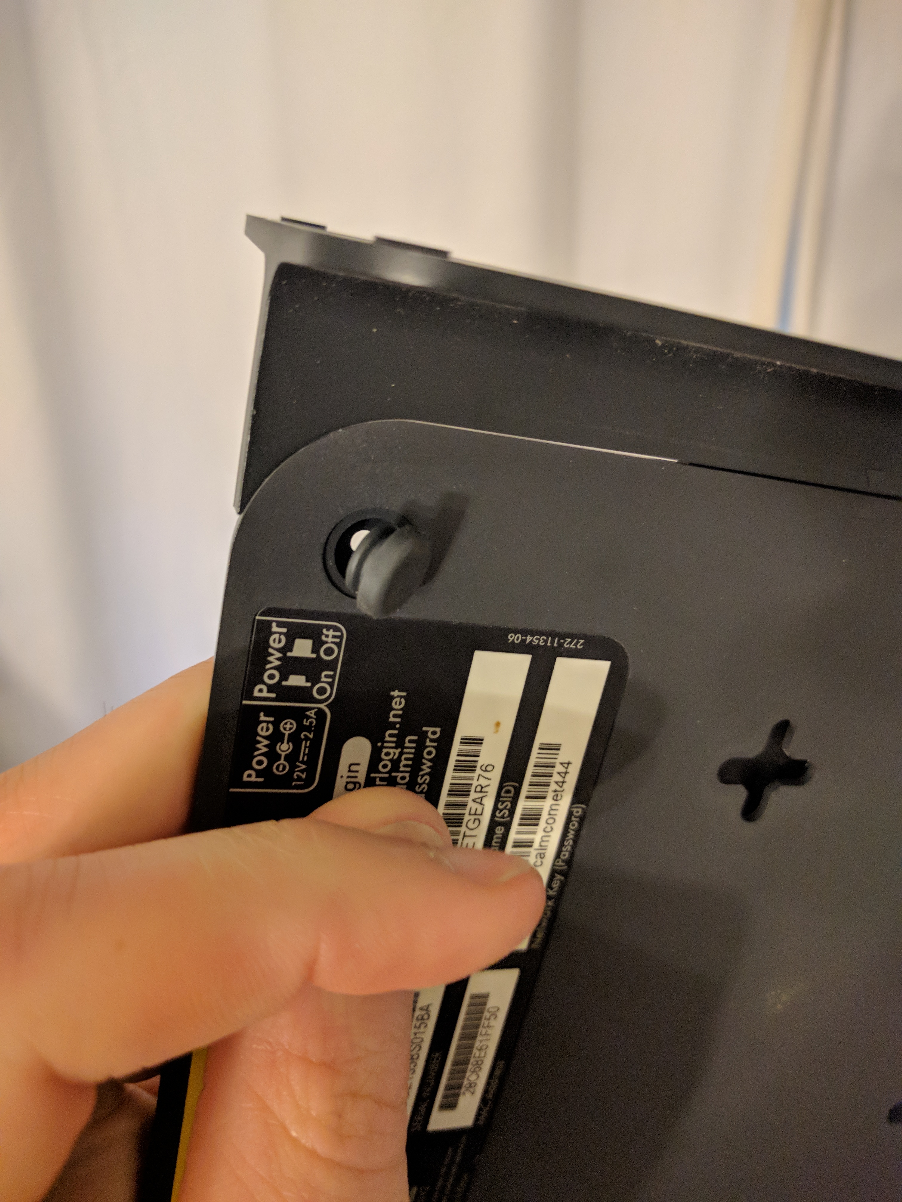
Well this is nice! the feet have retainers! Someone really put some care into the housing for this thing.
In the Hardware
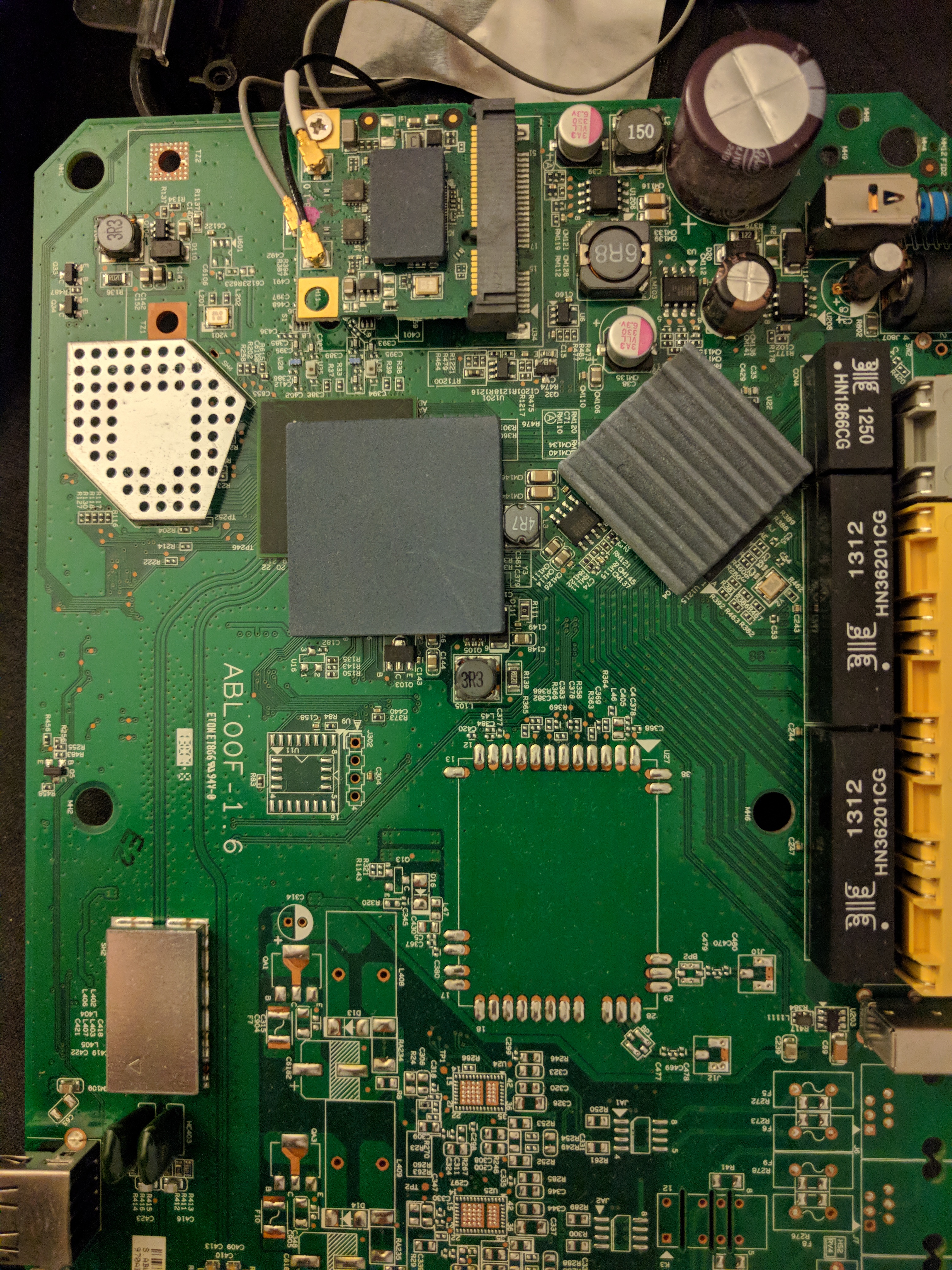
Front and center are two big ICs under thermal pads of some kind. I’ve got no idea why one is ridged and one is flat. Both are pretty stiff and old. On top is clearly a WiFi interface card, and to the far right are Ethernet jacks and what appear to be current sense transformers. Ethernet is a differential current protocol instead of voltage based, so an IC usually needs a transformer to convert between current and voltage. Some industrial protocols are also current based, I guess the losses are lower in long wires? The lower half of the board is nearly unpopulated. It looks like it supports two RJ-11 ports somehow. The function is unclear to me.
Just below the square heat pad is an empty footprint and a four-pin header! Is this the serial port?
A quick check:
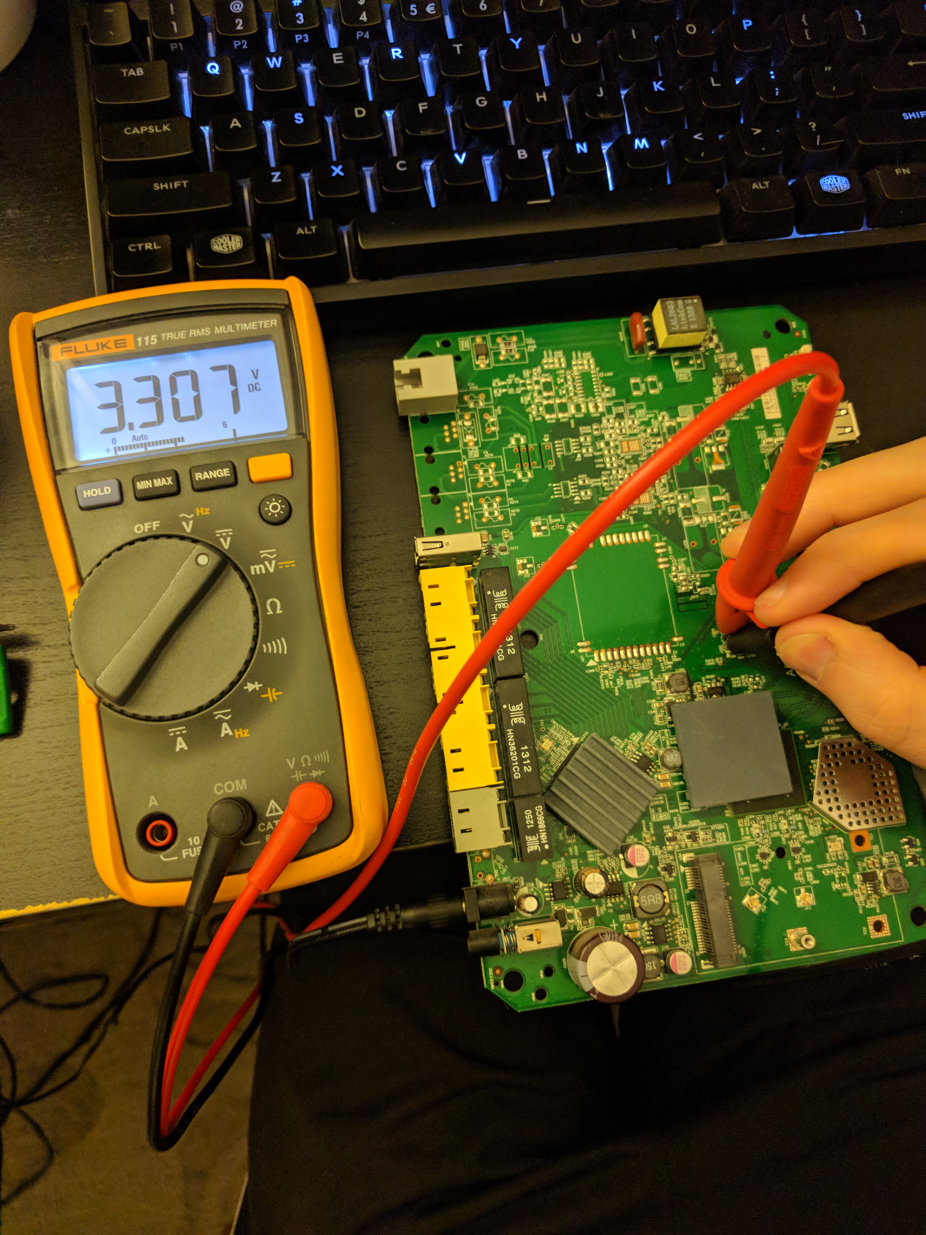
Logic level voltages. This is probably it, barring anything else that’s obvious. Let’s look closer:
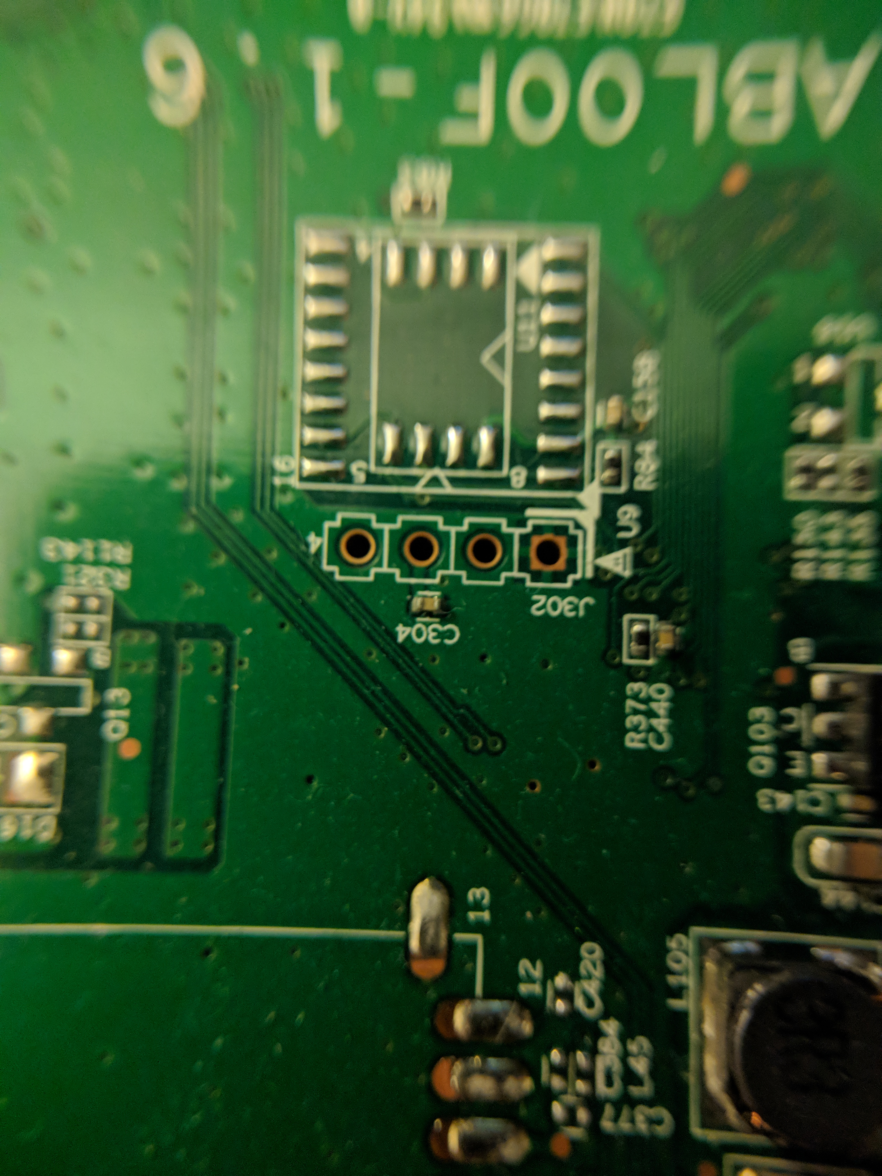
The pad on the far right goes to the groundplane, as shown by the thermal relief. The pad second from left is decoupled with a small capacitor, so that’s probably power.
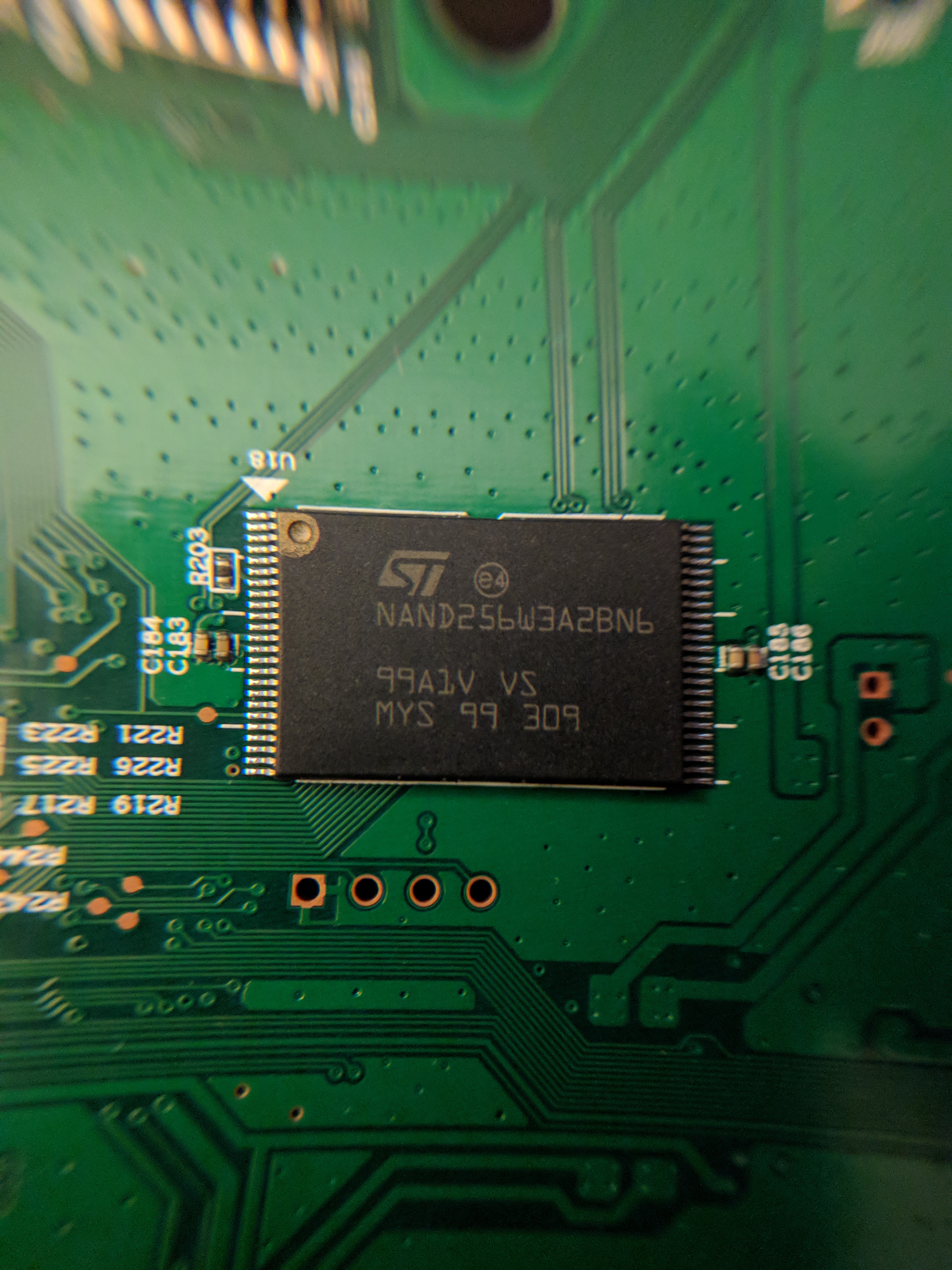
On the bottom, it’s clear that the other two pins head towards the large IC. This is almost certainly the serial port. Above the header is what I’m assuming is the NAND flash for the processor. It does say NAND on it.
This is where the dead firmware resides. So close I can physically touch it, but that’s not enough to reprogram it.
In the Software
One mediocre soldering job and a USB-serial converter later, let’s try and get something intelligible.
--- Miniterm on /dev/ttyUSB0  115200,8,N,1 ---
--- Quit: Ctrl+] | Menu: Ctrl+T | Help: Ctrl+T followed by Ctrl+H ---
HELO
CPUI
L1CI
HELO
CPUI
L1CI
DRAM
----
PHYS
ZQDN
PHYE
DINT
LASY
USYN
MSYN
LMBE
PASS
----
ZBSS
CODE
DATA
L12F
MAIN
NAN0
BTam
0001
NAN9
NAN3
RFS0
NAN5


CFE version 1.0.38-112.14 for BCM96362 (32bit,SP,BE)
Build Date: 2011年 12月 21日 星期三 18:16:05 CST (sunny@localhost)
Copyright (C) 2000-2011 Broadcom Corporation.

NAND flash device: name <not identified>, id 0x2075 block 16KB size 32768KB
External switch id = 53125
SC Debug: Setting RGMII TX_CLK DELAY at SWITCH IMP PORT!
SC Debug: Setting RGMII RX_CLK DELAY at SWITCH IMP PORT!
Chip ID: BCM6362B0, MIPS: 400MHz, DDR: 333MHz, Bus: 166MHz
Main Thread: TP0
Memory Test Passed
Total Memory: 67108864 bytes (64MB)
Boot Address: 0xb8000000

Board IP address                  : 192.168.1.1:ffffff00
Host IP address                   : 192.168.1.100
Gateway IP address                :
Run from flash/host (f/h)         : f
Default host run file name        : vmlinux
Default host flash file name      : bcm963xx_fs_kernel
Boot delay (0-9 seconds)          : 1
Board Id (0-5)                    : 96362ADVN2xh
Number of MAC Addresses (1-32)    : 11
Base MAC Address                  : 28:c6:8e:61:ff:50
PSI Size (1-64) KBytes            : 24
Enable Backup PSI [0|1]           : 0
System Log Size (0-256) KBytes    : 0
Main Thread Number [0|1]          : 0

*** Press any key to stop auto run (1 seconds) ***
Auto run second count down: 0
Enter NMRP_main
Scanning Flash Section 0...
Scanning Flash Section 1...
Scanning Flash Section 2...
Scanning Flash Section 3...
Scanning Flash Section 4...
Scanning Flash Section 5...
Scanning Flash Section 6...
Scanning Flash Section 7...
Scanning Flash Section 8...
Scanning Flash Section 9...
Scanning Flash Section 10...
Scanning Flash Section 11...
Scanning Flash Section 12...
NMRP:LISTENING ### No NMRP Server found ###
Scanning Flash Section 0...
Scanning Flash Section 1...
Scanning Flash Section 2...
Scanning Flash Section 3...
Scanning Flash Section 4...
Scanning Flash Section 5...
Scanning Flash Section 6...
Scanning Flash Section 7...
Scanning Flash Section 8...
Scanning Flash Section 9...
Scanning Flash Section 10...
Scanning Flash Section 11...
Scanning Flash Section 12...

***************************************************
	Sercomm Boot Version 1...0.6

***************************************************
Can not find  Block with Sercomm Sign!
Entering Download Mode : FW PID no exsit or corrupted.
Scanning Flash Section 0...
Scanning Flash Section 1...
Scanning Flash Section 2...
Scanning Flash Section 3...
Scanning Flash Section 4...
Scanning Flash Section 5...
Scanning Flash Section 6...
Scanning Flash Section 7...
Scanning Flash Section 8...
Scanning Flash Section 9...
Scanning Flash Section 10...
Scanning Flash Section 11...
Scanning Flash Section 12...

In Httpdownload...
I got the TX and RX pins right! It has a bootloader! It’s still got an IP stack! It can see the NAND chip! Maybe I’m not toast!
It looks like it’s waiting on a web download: point my desktop to the right IP address and:
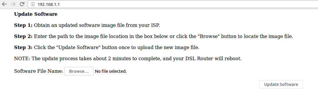
Put in the firmware image I pulled off Netgear’s website and:
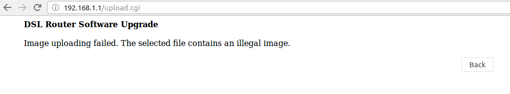
It doesn’t like it. Crap. Back to the serial console. Reboot the device and hit space a lot:
*** Press any key to stop auto run (1 seconds) ***
Auto run second count down: 1
web info: Waiting for connection on socket 0.␛[J
CFE>
CFE> help
Available commands:

sc_http             Sercomm http Upgrade Mode
sc_ramtest          SC Ram test Command
sc_tftp             sc tftp
sc_swreg            SC external switch reg operation api
sc_phyreg           SC phy reg operation api
sc_erase_force      SC force erase function, no matter if the block is OK or not
sc_init_marker      SC init clean marker in spare by given range
sc_led              SC LED Debug command
sc_gpio             SC GPIO Debug command
sc_nand_bad         Dump NAND Flash Block is bad or not
sc_flash_map        Dump NAND Flash Map defined in NVRAM
sc_lp               SC LoopBack Sample test Command
sc_upgrade          Sercomm Upgrade Mode
sc_nand_dump_oob    Dump NAND Flash OOB area
sc_nand_dump        Dump NAND Flash Content
sm                  Set memory or registers.
dm                  Dump memory or registers.
w                   Write the whole image start from beginning of the flash
e                   Erase NAND flash
r                   Run program from flash image or from host depend on [f/h] flag
p                   Print boot line and board parameter info
c                   Change booline parameters
i                   Erase persistent storage data
a                   Change board AFE ID
b                   Change board parameters
reset               Reset the board
help                Obtain help for CFE commands

For more information about a command, enter 'help command-name'
*** command status = 0
CFE>
Well, it’s got a menu, let’s try the TFTP mode:
CFE> sc_tftp y
Enter TFTP_SERVE_main
Scanning Flash Section 0...
Scanning Flash Section 1...
Scanning Flash Section 2...
Scanning Flash Section 3...
Scanning Flash Section 4...
Scanning Flash Section 5...
Scanning Flash Section 6...
Scanning Flash Section 7...
Scanning Flash Section 8...
Scanning Flash Section 9...
Scanning Flash Section 10...
Scanning Flash Section 11...
Scanning Flash Section 12...
	TFTP:LISTENING
Enter TFTP_handle_LISTENING_state
TFTP UPLOADING
Enter:SC_TFTP_SRV_main
Max retry,timeout
TFTP Load file error
Handle UPLOADING error
TFTP UPLOADING
Enter:SC_TFTP_SRV_main
RX a TFTP WRQ packet
TFTP SRV change to WRITE state
################	 1 MegaByte Got
################	 2 MegaByte Got
################	 3 MegaByte Got
################	 4 MegaByte Got
################	 5 MegaByte Got
################	 6 MegaByte Got
################	 7 MegaByte Got
################	 8 MegaByte Got
################	 9 MegaByte Got
################	 10 MegaByte Got
################	 11 MegaByte Got
################	 12 MegaByte Got
################	 13 MegaByte Got
################	 14 MegaByte Got
################	 15 MegaByte Got
################	 16 MegaByte Got
################	 17 MegaByte Got
################	 18 MegaByte Got
################	 19 MegaByte Got
################	 20 MegaByte Got
################	 21 MegaByte Got
################	 22 MegaByte Got
###########
Done! (0x16b1964 bytes, end addr 0x81cfbe50)
LOAD file OK=========!
LOAD File size:23796068(0x16b1964)
compressed image
GZIP compressed image ...
cal img checksum:0xffffffad
Compressed IMAGE CHECK ERROR
Handle UPLOADING error
TFTP UPLOADING
Enter:SC_TFTP_SRV_main
Max retry,timeout
Uploading a new image over that protocol just gives a checksum error, no matter which image I try from Netgear’s site. I’m stumped here, the checksums are apparently different for all the different images, but I’m not able to unpack the binary in order to dig further. I also have no idea what validation algorithm is being used, so the device currently sits dead until this can be cracked.